Posts

Showing posts with the label Benchwork

Terrain at Low's Bridge

Image
This afternoon, I added, carved, and shaped foam board for the Low's Bridge  scene on my layout. I first added two roughly one by two foot foam layers, each one inch thick. I then carved the rouh shape of the riverbank into the foam. After that, I used a rasp to shape and smooth the foam. The Low's Bridge area on my layout at the beginning of the afternoon. Test fitting the first layer of foam board. The first layer of foam board attached. Note the roughed in shape of the riverbed of the Pistcataquis River on the extreme left of the picture. The top layer of foam attached, making the foam board at Low's Bridge even with the foam board of the rest of the layout. The slope of the riverbank roughed in using a small knife. After initial shaping with the rasp. I then laid track at Low's Bridge and roughed up the foam board on the inland side of the track. This is how the Low's Bridge area looked by the end of the aft...

Foam Board Layout Surface

Image
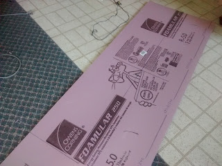
On Monday night, I cut and attached foam board to make a basic, flat, layout surface for my new layout. I used one inch thick foam board for this. Installation was fast and simple, and I did not have any problems with the foam board. I used a combination of wood glue and screws to secure the foam board on the layout. On the layout, I used a single two by eight foot piece of foam board to make up the main layout section, while I used some decent sized peices of foam that I had on hand in order to finish adding foam board to the layout. I still have to add more foam around Low's Bridge, as that area was attached to the main layout benchwork two inches lower than the rest of the layout, in order to make it easier to model the bridge. This afternoon, I'm hoping that I can build up the foam at Low's bridge so that tracklaying on the layout can comence. This is what I started out with - A large shhet of fresh foam board. This sheet is now the base for the what will be ...

Benchwork Pt. 3

Image
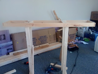
Last night I got the legs attached to the benchwork. It was a somewhat laborious project, and was made more difficult by the distinct downward slope of the floor in the room that I am building the layout in. With that complete, I can move on to adding a foam board layout surface. One end of the new benchwork. The legs at the far end of the layout had to be shortened by about half an inch to make the layout level. The other end of the layout. This contains the Low's Bridge layout section that I posted about the other day. A panoramic view of the benchwork, ready to have foam board attached.

Benchwork Pt. 2

Image
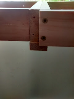
Yetserday evening and this morning I manged to get a lot of benchwork completed. I assembled the frames for the two longest sections of benchwork for the layout that I am building. The fames are just plain open grid frames made from one by three lumber. The frames went together fairly quickly and easily. I had some difficulties with the fame of the larger section as the lumber for those section was somewhat warped. It all went together and turned out fairly square in the end, however. Assembling the first corner of the smaller benchwork section that I built. Building the first corner of the larger benchwork section. The benchwork is held rogether by two wood screws screwed in at the corners. Attaching a crossbrace piece to the center of the larger scerion of benchwork. This was fairly difficult as the two long wood pieces were warped and had to be held very firmly in order rhat they would lie flat and the joint woth the crosspiece would be square. The finish...

New Layout Space

Image
I thought that I would post a few pictures of my new layout space. The new space is a medium sized fourth bedroom/storage room, of wich I have a 42 inch by 11 foot six space in which to build a layout. Unfortunately, due to the shape of the room, I cannot build the Penobscot Street Spur layout. I have however, been able to plan a different layout for the space, based on the Bangor & Aroostook's Greenville branch. I will post more about this plan sometime next week. This photo shows part of the longer wall of the layout space. Note the piles of lumber in preparation for the beginning of benchwork assembly. The other end of the layout space, showing the long wall as well as the shorter, 42 inch wall. The short wall will be the location of the Low's Bridge benchwork section that I posted about yesterday. 

Benchwork at Low's Bridge

Image
This afternoon, I worked on building a small becnhwork section tahy wiil eventually contain the location of Low's Bridge. Low's Bridge contained a flag stop platform and covered bridge. The location was situated on the Bangor and Aroostook's Greenville branch, and the covered bridge carried a local road over the Piscataquis river. I will be modeling this scene in a roughly one by two foot area. I had all the lumber lengths and foamboard I needed to build a basic frame and attach an initial layer of foam for this location on hand, so I decided to assemble the frame this afternoon. The frame was constructed from previously used one by threes. The dark brown patch in the center of the one board is brown paint from my last layout. Each board was connected to  another board at the corner using two small wood screws. The frame at the the end of assembly, and ready to have foam attached. I did not bother to adf any interior bracing as the frame is so small. ...

Layout Reassembly

Image
Today I reassembled the layout. It is now (almost) back to the way it was. The module connections that I designed really made it easy to put the layout back together. I can now start working on scenery. The corner module is cantilevered out from the town module. The bolt connections are quite strong as they are m providing most of the support for the corner module. Everything is back to normal on the layout. I ran a train to test that everything worked and, fortunately, everything worked fine. Next project is to shape the wall side of the cut on the countryside module.

Module Connections

Image
The benchwork on my layout is made up of three modules, which makes it necessary to have a way to connect and align the modules. To support the modules, I first attached a one by two inch board along the ends of the modules with legs. The picture below shows the module ends after the lower board was attached. The corner module was then placed on the board. After that, I drilled holes into both module end boards. These holes then had three inch long bolts inserted into them to align the modules, as shown in the photo below. I then screwed two small screws into the module connections to make sure the modules were secure. The picture above shows the module ends with the screws in place. This marks the end of benchwork on the scenic portion of the layout. 

Foam Board Added

Image
I added foam board to the layout q few days ago. I used one inch thick foam board to provide a layout base. The inch thick foam board is fairly sturdy and can easily support trains and scenery if it is decently braced underneath, I think.   I added foam board to two of the modules. The third module already had foam board attached to it. I started by marking the shape of the needed area onto a sheet of foam board. I then cut it out with a small kitchen knife. For the five by one foot module, I simply cut out a piece of foam to the exact size. For the corner module, I used two pieces of foam board that I cut to fit the module and then glued together using woof glue. My cat sat behind the layout and supervised everything. This is how the layout looks now with all of board attached. Now I can begin shaping basic landforms and laying track.

Benchwork Overview

Image
As I wrote earlier, I constructed benchwork over the weekend with the help of my father. Nothing special about the benchwork-just typical wood frame open grid. The benchwork is completely flat, and it is built in three modules. On module is five feet long and one foot wide, and another is six feet long and 18-30 inches wide. These modules both have legs. The third module is a corner module, roughly three by three feet in size. This module is supported by the other two modules and has one leg to support the rear corner. I will add a staging module at the end of the five by one foot module later. Here are some pictures of the completed modules. A side view of the completed five by one foot module. It forms one end of the layout.  A view of the same module, only this time from one corner. A view of the corner module. The rear leg supports the rear corner. The ends of the module are supported by the other two modules. I will write more about this later. The other mo...

Modular Benchwork

Image
Over the weekend, I constructed modular benchwork for a new layout. I built two sections, and attached them together. Here are some pictures of the finished benchwork. The finished benchwork. There are three modules in total. Looking at the benchwork from the other end of it. More about what all this is for later.

Building Benchwork-Part 2

Image
Yesterday I finished up benchwork construction on the Machais part of the layout and worked on attaching a base layer of foam insulation board o the layout. Construction of the wood section of the benchwork took a few hours. The first part of this section of benchwork was a six foot long section that extends into the center of the room. This section will evevntually be part of a larger peninsula with a turnback curve at the end, but for now it is just part of a large loop that represents the mainline around Machais. I started this section of benchwork with a 6 foot long by 18 inch wide frame of 1x3s and 2x3s. Nothing unusual about the construction, and it went together easily. However, attaching the legs was complicated as this section had to be mounted an inch below the rest of the layout as it represents part of the Machais River. This should have been simple, except I forgot to get the legs cut down an inch. Because of this, I had to support the frame up on to chunks of scrap ...