Posts

Showing posts with the label Grand Trunk New England Lines

Norway Revisited?

Longtime readers of this blog (are there any?) will know that I at one point had a layout based on the Grand Trunk New England Lines (GTNE) branch to Norway, Maine. This layout was built in modules but was disassembled when I moved in October. Recently, I've been thinking about layout design, and I've been trying to decide on a new layout to build. Yesterday, when I was looking through my phone at some of my older photos, I came across some photos of my layout based on Norway. Looking at them, I decided that I had a fairly good layout in that, so I've decided to revisit that layout and that prototype as a possible prototype for my next layout. You can find the original post on the track plan and layout design for my previous layout  here.  Or, you can access most posts on the topic of the GTNE by clicking on the Grand Trunk New England Lines category on the categories sidebar, though that may not get you to that particular post as it may have been posted before I added ca...

Layout Reassembly

Image
Today I reassembled the layout. It is now (almost) back to the way it was. The module connections that I designed really made it easy to put the layout back together. I can now start working on scenery. The corner module is cantilevered out from the town module. The bolt connections are quite strong as they are m providing most of the support for the corner module. Everything is back to normal on the layout. I ran a train to test that everything worked and, fortunately, everything worked fine. Next project is to shape the wall side of the cut on the countryside module.

Work to Resume on Layout

Image
I haven't posted for a long time, as is rather apparent. I'm still around, though the layout was partially disassembled recently and now has to be rebuilt. My cat is fascinated by the moving trains in a photo from early July.

A Few Pictures

Image
After working on the layout this afternoon, I ran a train to Norway and back. I thought I would share a few pictures showing a train running through the areas that I have recently worked on. This photo shows the train just after crossing Bird Brook and starting to round the curve out of the Norway terminus. The train approaches the camera. Though it is not the best quality photo, I think it gives some realistic heft to the locomotive. The train crosses through what will be a field and prepares to enter the future location of a forest hiding the entrance to staging. I will post about what I did on the layout later .

Hills and Terrain

Image
I know that I haven't posted much recently, but I did not get to work on the layout much last week. I wasn't particularly busy, it being summer vacation, but I could not get any layout work done for various reasons. However, this morning I was able to make good progress on the layout. I carved and shaped one side of a rise in the land of the third, countryside module and part of the corner module. This rise will eventually cover the entire countryside module except where the track passes through a shallow cut. One of my pet peeves about many layouts is that they are either far to flat or have exaggerated  topographical features, like very steep slopes or deep ravines, when most land areas are dominated by rather gentle topography. I have been guilty of this many times- Most of my previous layout attempts were completely flat. In Maine, however, most of the land is rolling terrain with countless slight rises and depressions in the land, so I have attempted to simulate this on ...

First Operations

Image
After test running the layout, I held a brief , informal, operating session with my Dad and Grandfather. The layout took about half an hour to operate informally, and was very enjoyable. It takes about two minutes for a train to operate between two ends of the layout at very slow speeds. We operated a three car train to Norway and spent around twenty to twenty five minutes switching the yard. We left town with a short, two car train. Here are some photos of the operating session. A Grand Trunk Western boxcar is set out at the lumberyard.  The locomotive heads to switch the team track. The locomotive returns from switching the lumberyard. Norway has been switched and the train back to Portland is being made on the passing siding. The train is ready to leave and the crew is taking a break before leaving for the return trip to Portland. The train begins to leave Norway yard. The train has arrived at the end of the layout. Loo...

First Run

This morning, I finished laying track with the help of my Dad. An advantage if a smaller layout like mine is that tracklaying can be completed in the span if a few days. I used plain Atlas code 83 flextrack for the track. After tracklaying was completed, I hooked the layout up to a power source and started to test the layout. An alco RS-3, currently primary locomotive, was run back and forth to test to see if the layout would actually work. The video above shows the first test run of the layout. I then put together a train of three cars and ran it from where staging will eventually be located to the town of Norway. The video is broken into three parts for ease of uploading them to the blog. This part of the video shows the train leaving from near the future staging area, running through the countryside module, and entering the corner module. This part of the video shows the train crossing Bird Brook and entering the yard at Norway.  This shows the train coming to...

Track Plan

Image
Here is the track plan for my layout. (Click on the image to enlarge it.) Each square represents nine square inches, while a distance of four squares represents a foot. The layout size is approximately nine by eight feet. A staging area will be added later, either in the form of a sector plate or a two track yard. Minimum radius is thirty inches on the mainline, and there are no grades. The two dotted lines that cross the layout represent the joints between the modules. The town module is six feet long, the two outer sides of the corner module are each three feet long, and the third, countryside, module is five feet long.  To anyone reading this who lives in Canada, happy Canada Day!

Why Norway, Maine?

Why am I modelling the Grand Trunk's Norway, Maine branch? This is probably the most important question as regards my layout. Norway was the smallest branch line terminal on the Grand Trunk New England Lines, and perhaps even in the entire state of Maine. Its yard (if it can be called that) and terminal area contained only five switches, as far as I know. This worked well for me as I wanted to model a small branch line terminal,. I also wanted to build my layout in a small space, and make it somewhat portable, as well. In addition, I already had a six foot long by thirty inch wide module constructed. As I played around with rough designs for Norway, it became apparent that the yard arrangement at Norway would fit on the module very easily. This was appealing as it did not require the construction of new benchwork for the town. As well as having a very small amount of track, the terminal at Norway was located in a very small area. The Norway terminal was located in a roughly...

In the Mail Today

In today's mail, I received a package containing the book Trackside Grand Trunk New England Lines with John Ames,  one of Morning Sun Books excellent color photo books. With the arrival of this book I can start major work on the layout and especially the Norway terminal module.

Why Grand Trunk New England Lines?

Please excuse the wordy nature of this post, but I think it is necessary to explain the concept and ideas behind my layout. First, I will explain a bit of historical background of the Grand Trunk New England Lines (GTNE), which seem to not be very well known. The Grand Trunk New England Lines ran between Portland, Maine, a mid sized port city on the Atlantic coast, and Montreal, P.Q.. Two branch lines in Maine, one to Lewiston Maine and the other to Norway, Maine, split of the main Portland to Montreal line. Portland was the main winter port for rail traffic on the Grand Trunk System until the 1920s.  Portland was therefore a major grain exporting port, with two terminal grain elevators, each with a capacity of over one million bushels of grain. During the early 1920s, the Grand Trunk system ran into debt problems due to its Pacific extension and was nationalized by the Canadian government. It thus became part of the Canadian National Railways. However, the Grand Trunk New En...

Stream Banks: Carved

Image
This afternoon, I finished the initial carving of the stream banks. While the stream banks are not ready for scenery yet, as I still have to smooth them out more, I think that they are starting to look good. I carved the banks following a photo of the stream leading to the Grand Trunk bridge in Norway. The picture shows stage stream as it looked while I was carving the banks. I used a knife to carve progressively smaller strips of foam from the edge of the stream bed to eventually attain a curved and natural looking stream bank. This picture shows the section of stream located in the viewing side of the layout after it had been carved. The rail bridge will be located where the carved sections end. Looking up the stream towards the bridge, as seen from the stream bed. Looking downstream towards the bridge. You can see the stream banks on the far side of the layout in the sides of the foreground. The stream banks look the most realistic in low level photographs. ...

Stream Banks Started

Image
This evening, I started work on carving and shaping the stream banks of Bird Brook. I only carved roughly a quarter of the banks, but it gives a good idea of how the entire stream will look like when I finish carving.y regular foam board carving knife was used  I based the topography of the stream banks based on Google street view photos of the area. An overall view of the stream location before I started carving the banks of the stream. An overview of the carved section of the stream. A view of the carved stream banks from the stream bed, looking towards where the railroad bridge will eventually be located. Looking at the bank from normal ground level. Looking from the opposite bank. I think that it is showing the beginnings of a believable stream. Hopefully, I will be able to work more on this over the weekend.

Module Connections

Image
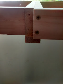
The benchwork on my layout is made up of three modules, which makes it necessary to have a way to connect and align the modules. To support the modules, I first attached a one by two inch board along the ends of the modules with legs. The picture below shows the module ends after the lower board was attached. The corner module was then placed on the board. After that, I drilled holes into both module end boards. These holes then had three inch long bolts inserted into them to align the modules, as shown in the photo below. I then screwed two small screws into the module connections to make sure the modules were secure. The picture above shows the module ends with the screws in place. This marks the end of benchwork on the scenic portion of the layout. 

A Stream on the Layout

Image
Yesterday, I carved out a stream bed on the corner module of the layout. This stream bed will eventually contain Bird Brook, a stream that ran past the Grand Trunk terminal in Norway, Maine. (As a side note, whenever I refer to Norway on this blog, I'm talking about the town in Maine, not the country. ) The Norway branch crosses Bird Brook on a small bridge just before it enters town. On my layout, the railroad will cross the stream on one end of the corner module. To model the stream bed for Bird Brook in my layout, I started by determining where it could be located by temporarily laying flextrack through the module. I then marked where a thirty scale foot long straight section could go without overly tightening the radius of the corner module's track.  I marked where a thirty scale foot long straight section could go without overly tightening the radius of the corner module's track. After this, I removed the track and drew an outline for the stream bed based on topog...

Foam Board Added

Image
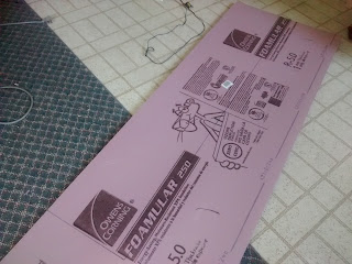
I added foam board to the layout q few days ago. I used one inch thick foam board to provide a layout base. The inch thick foam board is fairly sturdy and can easily support trains and scenery if it is decently braced underneath, I think.   I added foam board to two of the modules. The third module already had foam board attached to it. I started by marking the shape of the needed area onto a sheet of foam board. I then cut it out with a small kitchen knife. For the five by one foot module, I simply cut out a piece of foam to the exact size. For the corner module, I used two pieces of foam board that I cut to fit the module and then glued together using woof glue. My cat sat behind the layout and supervised everything. This is how the layout looks now with all of board attached. Now I can begin shaping basic landforms and laying track.